Difference between revisions of "Raspberry PWM LED Control"
Jump to navigation
Jump to search
| Line 6: | Line 6: | ||
[[File:PILEDPWM-2019-06-21.png|400px]] | [[File:PILEDPWM-2019-06-21.png|400px]] | ||
| + | We are going to use the Servoblaster software | ||
see {{Link|target=Self_Driving_RC_Car#Servo Interface - Servoblaster}} | see {{Link|target=Self_Driving_RC_Car#Servo Interface - Servoblaster}} | ||
| + | <source lang='bash'> | ||
| + | cat /run/servoblaster.status | ||
| + | p1pins=7,11,12,13,15,16,18,22 | ||
| + | p5pins= | ||
| + | |||
| + | Servo mapping: | ||
| + | 0 on P1-7 GPIO-4 | ||
| + | 1 on P1-11 GPIO-17 | ||
| + | 2 on P1-12 GPIO-18 | ||
| + | 3 on P1-13 GPIO-27 | ||
| + | 4 on P1-15 GPIO-22 | ||
| + | 5 on P1-16 GPIO-23 | ||
| + | 6 on P1-18 GPIO-24 | ||
| + | 7 on P1-22 GPIO-25 | ||
| + | </source> | ||
GPIO 24 has ServoId 6 so | GPIO 24 has ServoId 6 so | ||
Revision as of 22:39, 22 June 2019
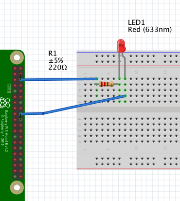
We'll use GPIO 24/ Pin 18 to drive the LED as in the default configuration of rc-dukes.
We are going to use the Servoblaster software see Self_Driving_RC_Car#Servo Interface - Servoblaster
cat /run/servoblaster.status
p1pins=7,11,12,13,15,16,18,22
p5pins=

Servo mapping:
     0 on P1-7           GPIO-4
     1 on P1-11          GPIO-17
     2 on P1-12          GPIO-18
     3 on P1-13          GPIO-27
     4 on P1-15          GPIO-22
     5 on P1-16          GPIO-23
     6 on P1-18          GPIO-24
     7 on P1-22          GPIO-25
GPIO 24 has ServoId 6 so
echo 6=120 > /dev/servoblaster
will set the LED to half bright

